
This article will present our company's customized 250kW-1050kWh Grid-connected Energy Storage System (ESS). The entire process, including design, installation, commissioning, and normal operation, spanned a total of six months. The objective of this project is to implement peak shaving and valley filling strategies to reduce electricity costs. Additionally, any excess electricity generated will be sold back to the grid, generating additional revenue. The customer expressed high satisfaction with our product solution and services.
Our Grid-connected ESS System is a tailored solution that provides reliable and efficient energy storage capabilities. It offers seamless integration with the grid, allowing for optimal load management and the utilization of peak-valley price differentials as per regional grid pricing policies.
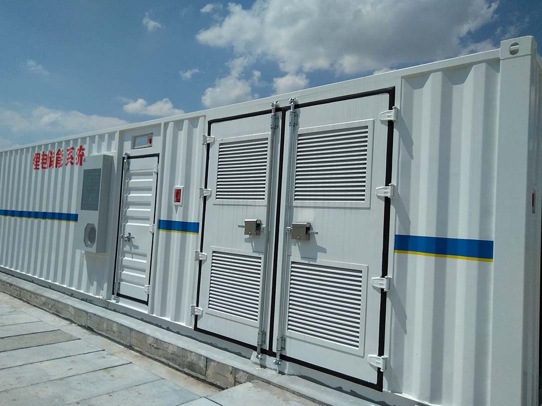
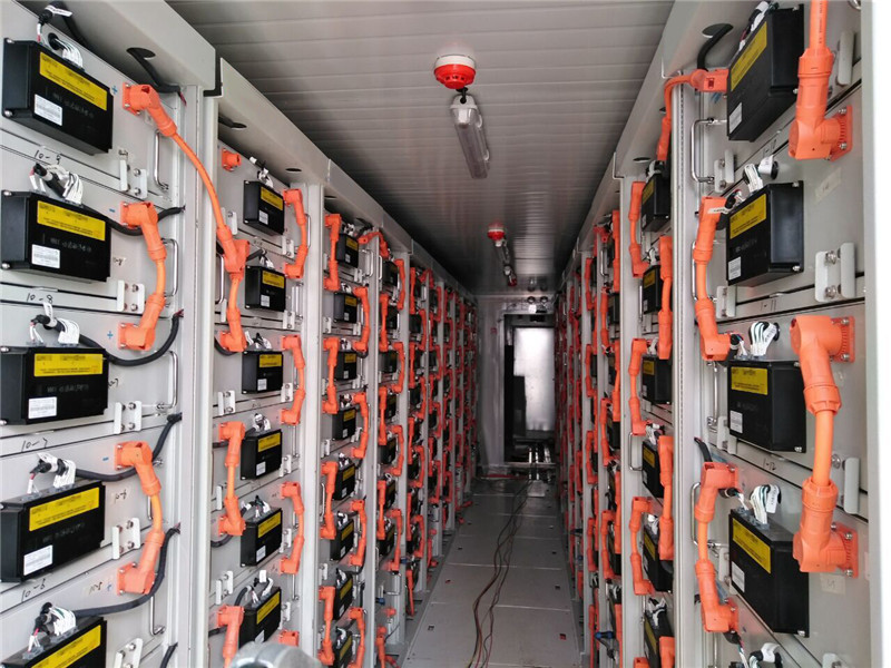
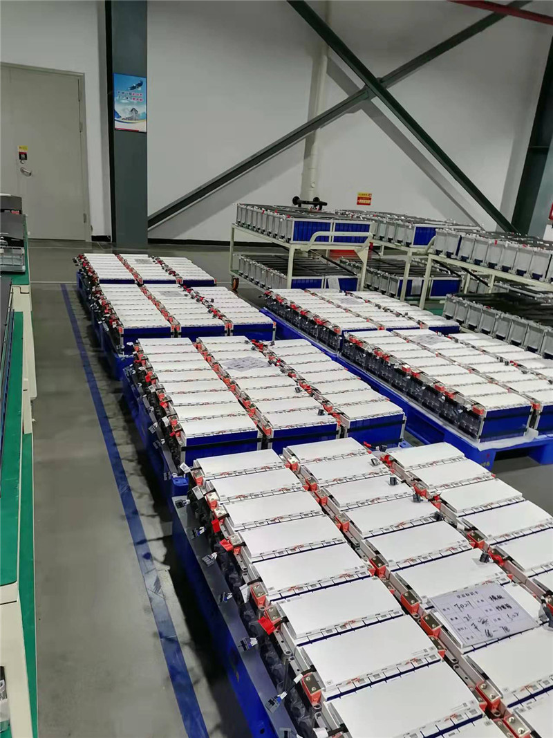
The system comprises various components, including lithium iron phosphate batteries, battery management systems, energy storage bidirectional inverters, gas fire suppression systems, and environmental control systems. These subsystems are ingeniously integrated within a standardized shipping container, making it versatile and suitable for a wide range of applications.
Some notable benefits of our Grid-connected ESS System include:
● Direct grid interconnection, facilitating dynamic response to power load fluctuations and market price differentials.
● Enhanced economic efficiency, enabling optimized revenue generation and investment payback periods.
● Active fault detection and rapid response mechanisms to ensure long-term operational safety.
● Modular design allowing for scalable expansion of battery units and energy storage bidirectional inverters.
● Real-time calculation of electricity consumption and cost optimization according to regional grid pricing policies.
● Streamlined engineering installation process, resulting in reduced operational and maintenance costs.
● Ideal for load regulation to minimize enterprise electricity expenses.
● Suitable for grid load control and stabilization of production loads.
In conclusion, our Grid-connected ESS System is a reliable and versatile solution that has received high praise from our satisfied customers. Its comprehensive design, seamless integration, and efficient operation make it a valuable asset for various industries and applications.
We will introduce this project through the following aspects:
● Technical Parameters of the Container Energy Storage System
● Hardware Configuration Set of the Container Energy Storage System
● Introduction to the Control of the Container Energy Storage System
● Functional Explanation of the Container Energy Storage System Modules
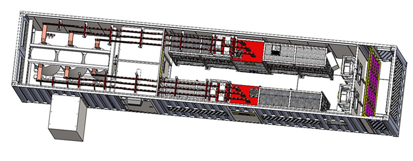
● Energy Storage System Integration
● Container Design
● System Configuration
● Cost-Benefit Analysis
1.Technical Parameters of the Container Energy Storage System
1.1 System parameters
|
Model number |
Inverter power (kW) |
Battery capacity (KWH) |
Container size |
weight |
|
BESS-275-1050 |
250*1pcs |
1050.6 |
L12.2m*W2.5m*H2.9m |
<30T |
1.2 Main technical index
|
No. |
Item |
Parameters |
|
1 |
System capacity |
1050kWh |
|
2 |
Rated charge/discharge power |
250kw |
|
3 |
Maximum charge/discharge power |
275kw |
|
4 |
Rated output voltage |
AC400V |
|
5 |
Rated output frequency |
50Hz |
|
6 |
Output wiring mode |
3phase-4wires |
|
7 |
Total current harmonic anomaly rate |
<5% |
|
8 |
Power factor |
>0.98 |
1.3 Usage environment requirements:
Operating temperature: -10 to +40°C
Storage temperature: -20 to +55°C
Relative humidity: not exceeding 95%
The usage location must be free from hazardous substances that may cause explosions. The surrounding environment should not contain gases that corrode metals or damage insulation, nor should it contain conductive substances. It should also not be filled with excessive humidity or have a significant presence of mold.
The usage location should be equipped with facilities to defend against rain, snow, wind, sand, and dust.
A hardened foundation should be selected. The location should not be exposed to direct sunlight during summer and should not be in a low-lying area.
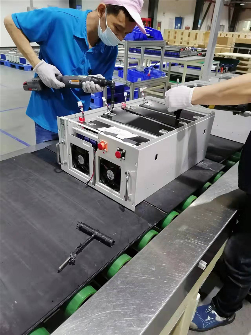
Hardware Configuration Set of the Container Energy Storage System
| No. | Item | Name | Description |
| 1 |
Battery System |
Battery cell | 3.2V90Ah |
| Battery box | 6S4P, 19.2V 360Ah | ||
| 2 |
BMS |
Battery box monitoring module | 12 voltage, 4 temperature acquisition, passive equalization, fan start and stop control |
| Series battery monitoring module | Series voltage, series current, insulation internal resistance SOC, SOH, positive and negative contactor control and node check, fault overflow output, touch screen operation | ||
| 3 |
Energy storage bidirectional converter |
Rated power | 250kw |
| Main control unit | Start and stop control, protection, etcTouch screen operation | ||
| Converter cabinet | Modular cabinet with built-in isolation transformer (Including circuit breaker, contactor, cooling fan, etc) | ||
| 4 |
Gas extinguishing system |
Heptafluoropropane bottle set | Containing pharmaceutical, check valve, bottle holder, hose, pressure relief valve, etc |
| Fire control unit | Including main engine, temperature detection, smoke detection, gas release light, sound and light alarm, alarm bell, etc | ||
| Network switch | 10M, 8 ports, industrial grade | ||
| Metering meter | Grid demonstration bidirectional metering meter, 0.5S | ||
| Control cabinet | Including bus bar, circuit breaker, cooling fan, etc | ||
| 5 | Container | Enhanced 40-foot container | 40-foot container L12.2m*W2.5m*H2.9mWith temperature control and lightning protection grounding system. |
Introduction to the Control of the Container Energy Storage System
3.1 Running state
This energy storage system categorizes battery operations into six distinct states: charging, discharging, ready static, fault, maintenance, and DC automatic grid connection states.
3.2 Charge and discharge
This energy storage system is capable of receiving dispatch strategies from the central platform, and these strategies are then consolidated and embedded in the dispatch control terminal. In the absence of any new dispatch strategies being received, the system will follow the current strategy to initiate either charging or discharging operations.
3.3 Ready idle state
When the energy storage system enters the ready idle state, the energy bidirectional flow controller and battery management system can be set to standby mode to reduce power consumption.
3.4 Battery are connected to the grid
This energy storage system offers comprehensive DC grid connection logic control functionality. When there is a voltage difference exceeding the set value within the battery pack, it prevents the direct grid connection of the series battery pack with excessive voltage difference by locking the corresponding contactors. Users can enter the automatic DC grid connection state by initiating it, and the system will automatically complete the grid connection of all series battery packs with proper voltage matching, without the need for manual intervention.
3.5 Emergency shutdown
This energy storage system supports manual emergency shutdown operation, and forcibly shuts down the system operation by touching the shutdown signal remotely accessed by the local ring.
3.6 Overflow trip
When the energy storage system detects a serious fault, it will automatically disconnect the circuit breaker inside the PCS and isolate the power grid. If the circuit breaker refuses to operate, the system will output an overflow trip signal to make the upper circuit breaker trip and isolate the fault.
3.7 Gas extinguishing
The energy storage system will start the heptafluoropropane fire extinguishing system when the temperature exceeds the alarm value.
4.Functional Explanation of the Container Energy Storage System Modules(contact with us to get the details)
5.Energy Storage System Integration(contact with us to get the details)
6.Container Design
6.1 Overall Design of the Container
The battery storage system fits a 40-foot container made of weather-resistant steel. It protects against corrosion, fire, water, dust, shock, UV radiation, and theft for 25 years. It can be secured with bolts or welding and has grounding points. It includes a maintenance well and meets crane installation requirements. The container is IP54 classified for protection.
Power sockets include both two-phase and three-phase options. The ground cable must be connected before supplying power to the three-phase socket. Each switch socket in the AC cabinet has an independent circuit breaker for protection.
The AC cabinet has a separate power supply for the communication monitoring device. As backup power sources, it reserves a three-phase four-wire circuit breaker and three single-phase circuit breakers. The design ensures a balanced three-phase power load.
6.2 Housing structure performance
The steel structure of the container will be constructed using Corten A high-weather resistant steel plates. The corrosion protection system consists of a zinc-rich primer, followed by an epoxy paint layer in the middle, and an acrylic paint layer on the outside. The bottom frame will be coated with asphalt paint.
The container shell is comprised of two layers of steel plates, with a filling material of Grade A fire-retardant rock wool in between. This rock wool filling material not only provides fire resistance but also has waterproof properties. The filling thickness for the ceiling and side walls should be no less than 50mm, while the filling thickness for the ground should be no less than 100mm.
The interior of the container will be painted with a zinc-rich primer (with a thickness of 25μm) followed by an epoxy resin paint layer (with a thickness of 50μm), resulting in a total paint film thickness of no less than 75μm. On the other hand, the exterior will have a zinc-rich primer (with a thickness of 30μm) followed by an epoxy resin paint layer (with a thickness of 40μm) and finished with a chlorinated plasticized rubber acrylic top paint layer (with a thickness of 40μm), resulting in a total paint film thickness of no less than 110μm.
6.3 Container color and LOGO
The complete set of equipment containers provided by our company are sprayed according to the highest fruit figure confirmed by the buyer. The color and LOGO of the container equipment are customized according to the requirements of the buyer.
7.System Configuration
| Item | Name |
Qty |
Unit |
|
| ESS | Container | 40 feet |
1 |
set |
| Battery | 228S4P*4units |
1 |
set |
|
| PCS | 250kw |
1 |
set |
|
| Confluence cabinet |
1 |
set |
||
| AC cabinet |
1 |
set |
||
| Lighting system |
1 |
set |
||
| Air conditioning system |
1 |
set |
||
| Fire fighting system |
1 |
set |
||
| Cable |
1 |
set |
||
| Monitoring system |
1 |
set |
||
| Low-voltage distribution system |
1 |
set |
||
8.Cost-Benefit Analysis
Based on an estimated calculation of 1 charge and discharge per day for 365 days a year, a depth of discharge of 90%, and a system efficiency of 86%, it is anticipated that a profit of 261,100 yuan will be obtained in the first year of investment and construction. However, with the ongoing progress of power reform, it is expected that the price difference between peak and off-peak electricity will increase in the future, resulting in an increasing trend of income. The economic evaluation provided below does not include the capacity fees and backup power investment costs that the company could potentially save.
|
Charge (kwh) |
Electricity unit price (USD/kwh) |
Discharge (kwh) |
Electricity unit price (USD/kwh) |
Daily electricity savings (USD) |
|
| Cycle 1 |
945.54 |
0.051 |
813.16 |
0.182 |
99.36 |
| Cycle 2 |
673 |
0.121 |
580.5 |
0.182 |
24.056 |
|
Total electricity saving one day(Two charge and two discharge) |
123.416 |
||||
Remark:
1. The income is calculated according to the actual DOD (90%) of the system and the system efficiency of 86%.
2. This income calculation only considers the annual income of the initial state of the battery. Over the life of the system, the benefits decrease with the available battery capacity.
3, annual savings in electricity according to 365 days two charge two release.
4. Revenue does not consider cost, Contact with us to get the system price.
The profit trend of peak shaving and valley filling energy storage system is examined with the consideration of battery degradation:
|
|
Year 1 |
Year 2 |
Year 3 |
Year 4 |
Year 5 |
Year 6 |
Year 7 |
Year 8 |
Year 9 |
Year 10 |
|
Battery capacity |
100% |
98% |
96% |
94% |
92% |
90% |
88% |
86% |
84% |
82% |
|
Electricity saving(USD) |
45,042 |
44,028 |
43,236 |
42,333 |
41,444 |
40,542 |
39,639 |
38,736 |
37,833 |
36,931 |
|
Total saving(USD) |
45,042 |
89,070 |
132,306 |
174,639 |
216,083 |
256,625 |
296,264 |
335,000 |
372,833 |
409,764 |
More details about this project, please contact with us.
Post time: Aug-29-2023


